The SIM represents a contract with a communications provider. The communications provider selling you the SIM has to either provide GSM coverage where you are, or have a roaming agreement with a company providing GSM coverage in your location. See the getting started page for additional information on SIM usage.
The module includes an internal GPS. The green one beside it will blink. If the shield joins the network successfully, the green LED will blink every seconds. It is the ideal solution for makers wanting to design IoT projects with minimal previous experience in networking.
FREE Shipping on eligible orders. Any compatible GSM module will work. SIMtrace - Duration: 11:09. You can get a pre-paid or post-paid SIM but we kinda like the pre-paid kind.
SIM card and the shield power supply. Save arduino sim card to get e-mail alerts and updates on your eBay Feed. Once the reader design is built, the open source software can be used to read from and write to the card. There are different kinds of GSM modules available in market. The easiest way to do this, is.
Simple Serial Communication. Out of sim cards only one pre-paid card working without any issue. What ever SMS sent through the post card sim we getting message as “Content Not Supported” at other end. Arduino Datalogger Shield.
The other pre-paid card not sending SMS at all. Connect the adapter to GSM module and turn it ON! Now wait for few seconds (say around 60sec) and see the. Here, our gsm module requires a volts input, so we supplying 12V,1A DC power to it. Some GSM modules require volts and some other needs only volts.
Guide on Booting GSM module: 1. This is meant for BYOD plans. SIM900A gsm module throught the arduino uno board. Power and flash the board. GPRS is useful for IoT applications outside establishments when there is no WiFi or network cable available. Blynk Library, it’s finally working ! Roland Pelayo January 2. The sim card interfaces consists of the series of the impedance matching circuits as we see there are six pins and there are eight pins some of the sim ’s.

All ground pins GND are connected together. I have bought off modules thus far and are really lost! The breakout board has a Mirco SIM seat the the back of the PCB. The arduino should give an AT Command to control it.
As usual, serial needs two pins that is Transmitter (Tx) and a Receiver (Rx). AT command is a command that begin with “AT”. Before using GSM modem make sure it is booted completely. Check it by inserting SIM and make a call to it.

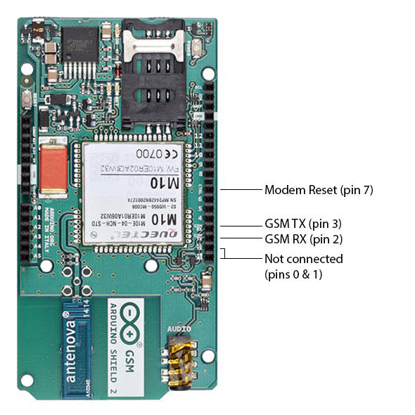
These are the serial UART connections which allow communication between the two modules. I wonder if anyone can help me. You must also check GSM Library for Proteus,. Please respond Thank you. Download (718) Electronics Engineering Calculators.
The GSM module requires a considerable amount of power to establish a network connection, and for operations. Smart- Card -Tool-pyResMan pyResMan is a free open source smartcard tool for JavaCard and other smart card. Cellular IoT Why Hologram Resources Pricing Store. The contents of the files are decoded and showed to the user.
The LM3give to module about 3. GPRS module with M5for SMS projects (part 1). When I assembled and tested the other one everything was fine. And change the code setting. Interface Cable SMA Male.
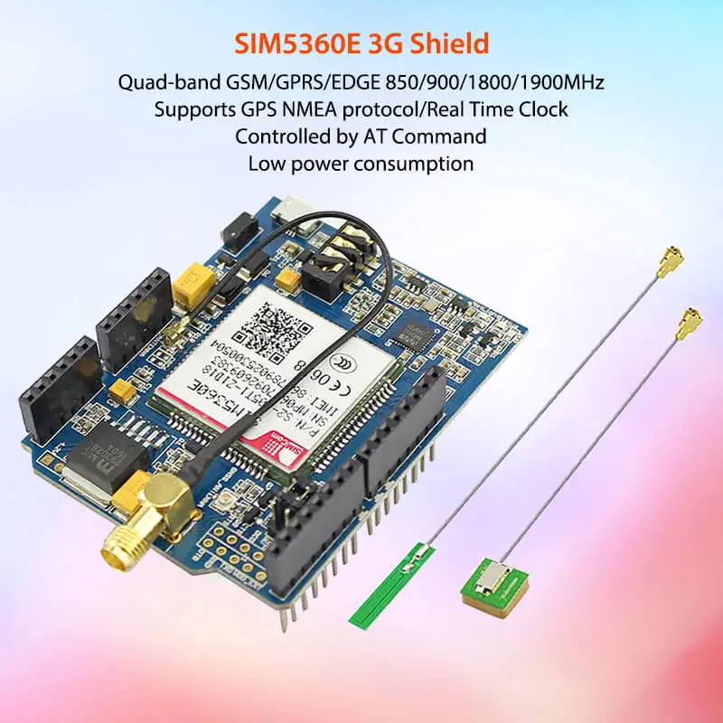
SIM Card holder and GSM Antenna - present onboard.
Hiç yorum yok:
Yorum Gönder
Not: Yalnızca bu blogun üyesi yorum gönderebilir.