This library allows you to control unipolar or bipolar stepper motors. To use it you will need a stepper motor , and the appropriate hardware to control it. Code samples in the reference are released into the public domain.
Advantage of using this driver are (a), Can change AMPs, (b) can stand high amp (More than 1Amp) and (c), can change the stepping easily. This common driver board is used in many 3D printers and CNC machines and simplifies the control of one or several. Stepper Motor Driver Board. In this article I’ll show you all you need to know to get started with stepper motors. Find more details, circuit schematics and source codes here.
A stepper motor consists of two main parts, a rotor and a stator. The rotor is the part of the motor that actually spins and provides work. The stator is the stationary part of the motor that houses the rotor. The circuit Diagram for the arduino stepper motor control project is shown above. To energise the four coils of the stepper motor we are using the digital pins and 11.
The motor will step one step at a time, very slowly. Finally the following command sets the speed that we wish the stepper motor to move, when we subsequently tell it how many steps to rotate. Dedicated driver circuit (and quite often a microcontroller) is needed to control the speed and direction of a stepper motor.
It has the ability to rotate a predefined number of steps, which makes it useful for precision mechanical devices. By using this driver you can Run high torque stepper motor which required up to 3Amps. To control motor type in commands in Serial Monitor, Set speed and steps follow instruction in Serial Monitor. Basically there are two types of stepper motors : bipolar and unipolar.
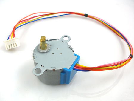
The bipolar stepper motor is a two-phase brushless motor which has two coils (windings), this motor has wires (wires for each coil). DC motor enable jumper. Leave this in place when using a stepper motor. The stepper motor used in this example is 28BYJ-(unipolar stepper motor ) which usually comes with its driver board. The L2Dubai H Bridge is base on l2Chip manufacture by ST Semiconductor.
INand INinput pins on the motor driver board. Connect these pins to digital outputs on your robots microcontroller. These chips keep the power that drives the motors separate from the power that is on the arduino. This project is an example how to drive a bipolar stepper motor with more accuracy.
Features: Constant speed mode (low rpms) Linear (accelerated) speed mode, with separate acceleration and deceleration settings. ARDUINO COMPATIBLES (386) BREAKOUT BOARDS (137) CIRCUIT PLAYGROUND (230). Arduino digital output pins to the driver module. Featured products like NEMA stepper motor and digital stepper motor driver have received high praise and had a good performance on market.
Wire connections are right becasue i checked it through oscilloscope and its generating a pattern according to given program code but the motor is still not running. Any stepper motor is great, but the big ones are amazingly impressive. The 28YBJ-stepper motor operates on 5Vdc and has built-in reduction gears. It has good torque for its size, but has relatively slow motion.
For that an external driver is required. These L298N driver boards will drive one stepper motor per board. After going through the project you can run or turn the motor to desired direction.
Let’s begin our tutorial and learn how to interface a stepper motor to Arduino. It can work with the power supply from 4. High accuracy controlling can. There are many ways to control stepper motors using an Arduino. In this tutorial we will see how to control a Nema size stepper motor using an Analog Joystick. To connect the stepper to the UNO we will be using the popular and inexpensive Easy Driver controller board.
Unfortunately, they are now $each and very difficult to find. Typical stepper motors consist of a rotating permanent magnet (rotor) surrounded by electromagnets (stator). Ancak kod yazılımında sorun yaşamaktayım.
Kullanmış olduğum motoru ters yönde hareket ettirememekteyim. Aşağıda kullandığım kodlar yazılı. Forum da cevap bulamadığım için buraya yazıyorum.
The diagram to the left shows the wires connected to the motor. Plug the motor into the driver board. IC (a LMxxx), and the driver is connected to Arduino. Since I do not have a driver at han I need to convert the circuit so it works with transistors instead. Most stepper drivers offer something called microstepping, and the Big Easy Driver is no exception.
As I mentioned before, steppers have that minimum movement called a step. The Motor Shield is able to drive servo motors , and has half-bridge outputs for stepper motors or full H-bridge motor outputs or half-bridge drivers , or a combination.
Hiç yorum yok:
Yorum Gönder
Not: Yalnızca bu blogun üyesi yorum gönderebilir.